
Account
-

Safe payment options
We only work with the most secure payment systems.
-

Product return within 30 days
We do our very best to keep our customers happy.
No products in the cart.
You dont have any products in your cart yet, add a few products to experience this experience.
Add $500.00 to cart and get free shipping!
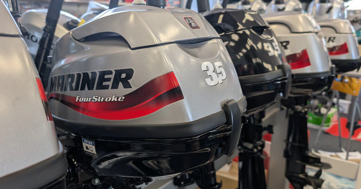
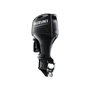
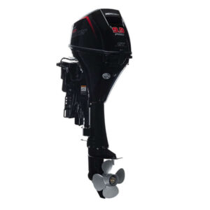
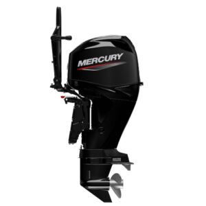
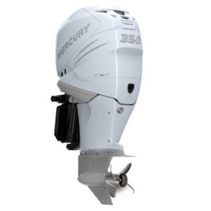
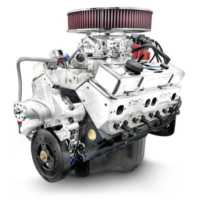
Professional Guidance for Outboard Motor and Marine Engine Installation
Pre-Installation Planning
Proper planning prevents costly mistakes. Before beginning any marine engine installation, complete the following:
Pre-Installation Checklist
| Item | Details |
|---|---|
| Transom Inspection | Check for rot, cracks, or flexing. Repair or reinforce before installation. |
| Shaft Length Verification | Measure from transom top to anti-ventilation plate. Common: 15″ (short), 20″ (long), 25″ (extra-long), 30″ (ultra-long). |
| Mounting Hardware | Stainless steel bolts, washers, lock nuts, backing plates, marine sealant (3M 5200). |
| Steering System | Confirm compatibility (mechanical cable or hydraulic). |
| Control Cables | Verify correct length (measure from control box to engine + service loop). |
| Wiring Harness | Must match engine model, year, and gauge package. |
| Fuel System | Clean tank, new water-separating fuel filter, correct primer bulb orientation (arrow toward engine). |
| Battery | Marine starting battery, fully charged, correct CCA rating for engine size. |
| Propeller | Correct pitch, diameter, and material for your application. |
| Safety Equipment | Fire extinguisher, kill switch lanyard, proper flotation. |
Outboard Motor Installation
Mounting Height Guide
The anti-ventilation plate (the flat plate just above the propeller) is the critical reference point for mounting height.
How to Measure
Place a straight edge along the bottom of the hull
Extend it to the transom
Measure from the straight edge to the top of the anti-ventilation plate
Recommended Heights by Boat Type
| Boat Type | Recommended Height |
|---|---|
| Standard Recreational | Anti-ventilation plate even with hull bottom |
| Performance / Bass Boat | 1–2 inches above hull bottom |
| Bay Boat / Shallow Water | 1–2 inches above hull bottom |
| Heavy / Work Boat | 0–1 inch below hull bottom |
| Pontoon / Deck Boat | Even with hull bottom or 1 inch below |
Effects of Incorrect Height
| Height | Problem |
|---|---|
| Too Low | Excessive drag, reduced top speed, poor fuel economy, water spray over transom |
| Too High | Propeller ventilation (cavitation), poor hole shot, overheating at high speed |
Transom Preparation
Step 1: Inspect Transom Condition
Check for soft spots (indicating rot)
Tap with hammer – solid sound indicates good condition
Check for cracks around mounting holes
Step 2: Reinforce if Necessary
Wood transom: Use aluminum or composite backing plates (minimum 1/4″ thick, 6″ x 6″)
Fiberglass transom: Ensure no delamination; use backing plates
Step 3: Mark and Drill Mounting Holes
Position engine centered on transom
Use engine bracket as template to mark holes
Drill holes slightly larger than bolt diameter (to allow for sealant)
Seal all holes with marine-grade sealant before bolting
Step 4: Bolt Engine to Transom
| Bolt Size | Torque Specification |
|---|---|
| 1/2″ (12mm) | 40–50 lb-ft (55–68 Nm) |
| 5/8″ (16mm) | 60–70 lb-ft (80–95 Nm) |
| 3/4″ (19mm) | 80–90 lb-ft (108–122 Nm) |
Use stainless steel bolts with nylon lock nuts
Apply anti-seize to threads
Use backing plates inside transom for load distribution
Apply sealant between transom and mounting bracket
Steering Connection
Mechanical Cable Steering
| Step | Action |
|---|---|
| 1 | Lubricate cable and steering tube |
| 2 | Connect steering link to engine tiller arm |
| 3 | Adjust for full travel left and right |
| 4 | Test for smooth operation before launching |
Hydraulic Steering (Seastar / BayStar)
| Step | Action |
|---|---|
| 1 | Mount helm pump at console |
| 2 | Route hydraulic hoses to engine (avoid sharp bends) |
| 3 | Fill system with approved fluid |
| 4 | Bleed air from system (follow manufacturer procedure) |
| 5 | Cycle lock-to-lock 20–30 times to remove air |
| 6 | Check for leaks |
| 7 | Verify steering effort is smooth and consistent |
Control Cables
Cable Length Measurement
Measure from control box mounting location to engine
Add service loop length (2–3 feet / 60–90 cm)
Add engine tilt allowance (1–2 feet / 30–60 cm)
Round up to nearest available cable length
Cable Routing
Avoid sharp bends (minimum radius 8 inches / 20 cm)
Use smooth curves, not 90-degree angles
Secure with cable ties every 12–18 inches
Avoid routing near exhaust or moving parts
Cable Adjustment
| Step | Action |
|---|---|
| 1 | Disconnect cables from engine |
| 2 | Place control box in neutral |
| 3 | Adjust cable barrels so pins align with engine attachment points |
| 4 | Reconnect and test shift engagement |
| 5 | Verify engine starts only in neutral (neutral safety switch) |
| 6 | Test forward and reverse engagement |
Wiring & Instrumentation
Wiring Harness Installation
| Step | Action |
|---|---|
| 1 | Route harness from engine to helm, avoiding sharp edges and heat sources |
| 2 | Use grommets where passing through bulkheads |
| 3 | Connect to key switch, gauges, and controls per wiring diagram |
| 4 | Verify ground connections (critical for electronic engines) |
| 5 | Secure harness with zip ties every 12–18 inches |
| 6 | Test all functions before launching |
Gauge Installation
| Gauge Type | Connection |
|---|---|
| Tachometer | Signal from engine harness; set to correct cylinder/pole setting (usually 6P for V6, 4P for inline 4) |
| Speedometer | Pitot tube connection or GPS signal |
| Water Pressure | Connect to engine water pressure port (typically 1/8″ NPT) |
| Trim Gauge | Signal from trim sender on engine bracket |
| Fuel Gauge | Connect to fuel tank sender (requires separate wiring) |
NMEA 2000 Network (Digital Integration)
For modern outboards (Mercury, Yamaha, Suzuki, etc.):
| Component | Purpose |
|---|---|
| NMEA 2000 Backbone | Connects engine to displays |
| Engine Gateway | Converts engine data to NMEA 2000 |
| Multifunction Display (MFD) | Displays engine data (RPM, fuel burn, trim, faults) |
Inboard Marine Engine Installation
Engine Alignment
Proper alignment between engine and shaft coupling is critical for longevity.
Alignment Procedure
| Step | Action |
|---|---|
| 1 | Install engine on mounts (do not fully tighten) |
| 2 | Slide shaft coupling onto transmission output flange |
| 3 | Use feeler gauges to check gap between coupling halves |
| 4 | Adjust engine mounts until gap is even (within 0.003 inches / 0.08 mm) |
| 5 | Tighten engine mounts to specification |
| 6 | Re-check alignment after tightening |
| 7 | Bolt coupling halves together with proper torque |
Signs of Misalignment
| Symptom | Cause |
|---|---|
| Vibration at certain RPM | Misalignment |
| Premature shaft seal failure | Angular misalignment |
| Coupling bolt breakage | Parallel misalignment |
| Transmission noise | Excessive misalignment |
Cooling System (Raw Water / Closed Cooling)
Raw Water Cooling
| Component | Installation Notes |
|---|---|
| Water Pickup | Ensure unobstructed flow; use sea strainer |
| Water Pump | Install with proper belt tension |
| Thermostat Housing | Use OEM gaskets and sealant |
| Hoses | Marine-grade reinforced hose; double-clamp all connections |
Closed Cooling (Heat Exchanger)
| Component | Installation Notes |
|---|---|
| Heat Exchanger | Mount with vibration isolation |
| Coolant | Use marine antifreeze (propylene glycol) |
| Expansion Tank | Mount above heat exchanger |
Exhaust System
| Component | Installation Notes |
|---|---|
| Exhaust Manifolds | Use new gaskets; torque to specification |
| Risers / Elbows | Inspect for corrosion; use marine-grade components |
| Hoses | Use marine exhaust hose (wire-reinforced) |
| Water Injection | Ensure water is injected after exhaust elbow to prevent backflow |
Post-Installation Checklist
Before launching, verify the following:
| Item | Check |
|---|---|
| Engine Mounting | Bolts torqued, sealant applied |
| Steering | Full travel left/right, smooth operation |
| Controls | Neutral start only, forward/reverse engagement |
| Wiring | All connections secure, no exposed wires |
| Battery | Secured, terminals protected |
| Fuel System | No leaks, primer bulb firm |
| Cooling | Water intake clear, hoses secure |
| Propeller | Securely torqued, cotter pin installed |
| Kill Switch | Lanyard attached, safety function tested |
| Safety Gear | Fire extinguisher, life jackets onboard |
First Launch & Break-In
Pre-Launch Checks
Turn battery switch on
Test kill switch function
Check fuel system for leaks
Lower engine to operating position
Verify water intake is submerged
First Start (On Water or with Flushing Muffs)
| Step | Action |
|---|---|
| 1 | Squeeze primer bulb until firm |
| 2 | Place control in neutral |
| 3 | Turn key to “on” (listen for fuel pump prime) |
| 4 | Start engine |
| 5 | Immediately verify water flow from tell-tale (pee hole) |
| 6 | Check oil pressure (if equipped) |
| 7 | Listen for unusual noises |
| 8 | Inspect for fuel or water leaks |
Break-In Procedure
Follow manufacturer-specific break-in procedures. General guidelines:
| Period | Action |
|---|---|
| First Hour | Vary RPM; avoid prolonged idling; do not exceed 3,000–4,000 RPM |
| Next 2–3 Hours | Gradually increase RPM; avoid sustained wide-open throttle (WOT) |
| After 10 Hours | Change oil (four-stroke); inspect gearcase oil |
| After 20 Hours | Check propeller torque; inspect all connections |
Common Installation Mistakes
| Mistake | Consequence | Prevention |
|---|---|---|
| Incorrect mounting height | Poor performance, ventilation, overheating | Measure before drilling |
| No transom backing plates | Transom damage, engine loss | Use backing plates for all installations |
| Improper cable length | Binding, poor shifting | Measure twice; add service loop |
| Loose battery connections | Starting issues, electrical failure | Torque connections; use corrosion protection |
| No sealant on mounting bolts | Water intrusion, transom rot | Use marine sealant on all through-hull bolts |
| Steering not bled (hydraulic) | Erratic steering, air in system | Bleed thoroughly; cycle lock-to-lock |
| Propeller not torqued | Prop loss, hub damage | Torque to specification; use cotter pin |
| No fuel water separator | Contaminated fuel, engine damage | Install water-separating fuel filter |
Professional Installation
While DIY installation is possible for experienced boaters, professional installation is strongly recommended for:
New engine warranty: Most manufacturers require installation by a qualified marine technician for warranty validity
Complex rigging: Digital controls, NMEA 2000 networks, and integrated electronics
High-horsepower engines: 250 HP and above require precise rigging for safety
Inboard engines: Alignment, cooling, and exhaust systems require specialized knowledge
Recommended Installers
We can recommend qualified marine installers in your area. Contact us for a referral.
| Region | Referral Available |
|---|---|
| Poland (Tricity area) | ✅ Yes |
| Rest of Poland | ✅ Limited |
| European Union | Contact for recommendation |
Safety Precautions
| Hazard | Precaution |
|---|---|
| Fuel | Work in well-ventilated area; no open flames; disconnect battery |
| Electrical | Disconnect battery before working on wiring |
| Heavy Components | Use proper lifting equipment; outboards weigh 100–400+ kg |
| Sharp Edges | Wear gloves; use grommets for wiring pass-throughs |
| Propeller | Remove propeller when testing on land; never run engine with prop installed out of water |
| Carbon Monoxide | Never run engine in enclosed space |
Need Help?
Our technical support team is available to assist with marine installation questions.
| Department | Contact | Best For |
|---|---|---|
| Technical Support | help-desk@electricalmarinesolutions.pl | Installation questions, troubleshooting |
| Sales | sales@electricalmarinesolutions.pl | Engines, parts, rigging components |
| Finance | finance@electricalmarinesolutions.pl | Invoicing, payments |
Before contacting us, please have ready:
Engine make, model, and serial number
Boat make, model, and year
Photos of your transom, engine bay, or current setup
Specific questions or issues